Key Points:
- Series circuits and parallel circuits have a lot of differences between themselves. These greatly affect the circuit.
- Series circuits cannot support all the components if one component gets damaged. But parallel configuration keeps all the other components running even after a malfunction.
- Series configuration keeps the current flow same but the voltage different, but in case of a parallel circuits, it is the complete opposite.
Electrical devices can be linked in either a series or parallel configuration. A series circuit is one in which two or more components share a common node and share the same current. Components in a parallel circuit, on the other hand, share two common nodes.
A series circuit is distinguished by the fact that current may only travel in one direction. However, a parallel circuit is distinguished by the fact that all components are linked to the same set of electrically common terminals. Apart from these there are other key factors such as current flow, voltage, resistance etc. which effects the circuit because of its configuration.
In this article, I will discuss in detail about parallel vs series circuit, their key differences as well as how the configuration of either series or parallel, can affect the circuit in various ways.
What Is a Series Circuit?
When the flow of current is the same through all of the circuit’s components, it’s called a series circuit. The current in a series circuit has only one route.
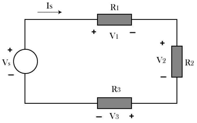
The current and voltage relationships in a series circuit are the inverse of those in a parallel circuit. Each series element’s current is the same and equal to the source current (Is).
The voltage across each series element (V1, V2, V3), on the other hand, fluctuates depending on the impedance (in this case, the resistance) of each element. The voltage provided by the source (Vs) is equal to the total of the individual voltage drops across each series element, according to Kirchhoff’s Voltage Law (KVL).
Advantages of Series Circuits
- Circuits in series configuration are comparatively easier to understand.
- Due to the voltage getting divided, it does not overheat quickly.
- It has a comparatively higher output voltage; therefore, more power appliances can be integrated.
- It carries the same current throughout the entire circuit.
Disadvantages of Series Circuits
- Circuit resistance increases as the total number of components in the circuit grows.
- If a single point in the circuit fails, the entire circuit will stop working.
What Is a Parallel Circuit?
A parallel circuit is one in which the current flows across two or more pathways. All of the components in a parallel circuit have the same voltage.
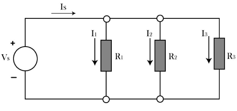
The voltage across each element in a parallel circuit is the same and equal to the source voltage (Vs), and the current through each element (I1, I2, I3) varies depending on the impedance (in this case, resistance) of each element.
The overall current coming from the source (Is) is equal to the sum of the individual currents flowing through each parallel element, according to Kirchhoff’s Current Law (KCL).
Advantages of Parallel Circuits
- In a parallel circuit, if one component fails, the current continues to flow through the other components, allowing the remaining components to function properly.
- Because the voltage across each component in a parallel circuit is the same, all components function efficiently.
- You may quickly connect or detach a new component in a parallel circuit without impacting the operation of another component.
Disadvantages of Parallel Circuits
- An additional voltage source cannot be used in a parallel circuit.
- The connecting of a parallel circuit necessitates a large number of wires.
What Are the Differences Between Parallel and Series Circuits?
There are several key factors that differ between a parallel circuits and a series circuit apart from varying degree of passing electricity and voltage. So, what is the difference between a series and a parallel circuit? They are displayed in the chart below. Let’s take a look.
Parallel VS Series Circuits: Chart
| Features | Series Circuits | Parallel Circuits |
| Common Nodes | 1 Node | 2 Nodes |
| Voltage | Divided among components | All components receive the same voltage |
| Current | All components receive the same current flow | Divided among components |
| Resistance | Increases | Decreases |
| Capacitance | Decreases | Increases |
| Inductance | Increases | Decreases |
| Limitation | Power decreases due to low voltage on distant components. | Power remains the same as all components share the same voltage. |
| Effect on Other Components | Damaged component hinders current flow. | Damaged component does not hinder current flow. |
| Appearance | 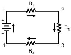 | 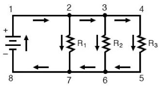 |
How Does the Circuit Configuration Affect the Circuit?
Yes, the circuit configuration definitely affects the entire circuit in various manners. It depends on the factors mentioned above as well the components that have been used in the circuit.
Let’s take a detailed look at those effects.
Common Nodes:
There is no other connection between series components because they share a single node.
In basic words, one component’s head links to another’s tail, and there is no other connection between them.
The heads of all parallel components, on the other hand, share one common node, while the tails share other common nodes.
Voltage:
The difference between series and parallel connection in voltage is that, the incoming voltage is split into the components of a circuit in series configuration.
On the other hand, the voltage between parallel components is always the same as the supplied input voltage. These have to be kept in mind while This is an important law which has to be used while wiring outlets in series vs parallel.
Current:
In circuits with a series arrangement, the current is always the same. The current, on the other hand, is shared among the parallel connected devices.
Resistance:
To produce the equivalent resistance, series resistors are simply added. However, for the proper solution of parallel resistors, a special formula is required.
Capacitance:
Due to the voltage difference between each capacitor, when capacitors are connected in series, their total capacitance decreases.
The charge that is stored as a result of this voltage decreases as well. The total capacitance of capacitors in a parallel circuit improves and becomes equal to the sum of the individual capacitors’ values.
Inductance:
In a series system, the total inductance of two or more inductors is the sum of their individual values.
The total inductance of the parallel circuit’s parts decreases, and it is always less than the inductance of the individual parts.
Limitation:
A series circuit, while having the ability to add an additional voltage source, it cannot supply the same current throughout the circuit.
Whereas, a parallel circuit does not have the functionality of adding an additional voltage source, it can provide same current flow throughout its components.
Effect on Other Components:
A faulty component in a series circuit opens the total circuit, thus stopping current flow. A broken component in a parallel circuit opens the branch, while the remaining components of the circuit remain intact.
These are the key factors which differentiate between a series circuit vs a circuit is parallel configuration. They must all be taken into consideration before continuing with any electrical tasks such as, how to convert 3 phase to single phase 220v etc.
Summary
In this article, I have explained in detail, the key differences between parallel vs series circuit. I have also brought up how those factors affect a circuit, and its components.
This article also showcases both the advantages and disadvantages of each circuit configuration. You must choose which configuration to use according to the components that you wish to integrate into your circuit, as well as the specification of your voltage supply.


![How to Fix Hole in Ceiling from Light Fixture? [Full Guide]](https://wiringsolver.com/wp-content/uploads/2021/09/How-to-Fix-Hole-in-Ceiling-from-Light-Fixture.webp)


