Chassis wiring is usually used to power and controls the various components of a vehicle. Power transmission wiring refers to the electrical system that is used to transmit electrical power from one location to another.
The differences include the type of wiring used, the voltage and current levels involved and the distances over which the electrical current is transmitted.
In this article, we will explore the differences between Chassis Wiring Vs Power Transmission Wiring in more detail.
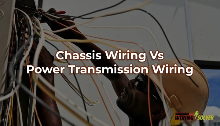
What are the Differences Between Chassis Wiring and Power Transmission Wiring?
There are several key sectors where chassis wiring differs from power transmission wiring. Such as amperage capacity, wire gauge, resistance, etc.
Let’s summarize the differences between these two wiring methods in the table provided below for the comfort of the reader.
Chassis Wiring Vs Power Transmission Wiring At a Glance
Differences | Chassis Wiring | Power Transmission Wiring |
Gauge | Smaller gauge wire | Larger gauge wire |
Voltage and current levels | Low voltage, high current | High voltage, low current |
Distance: | Short distances | Long distances |
Purpose | Powering and controlling vehicle components | Transmitting electrical power from one location to another |
Applications | Automobiles, aircraft, boats | Power plants, electrical grids, transmission lines |
Protection measures | Fuses, circuit breakers, grounding | Insulators, lightning protection, grounding |
Examples | Engine, headlights, dashboard | Insulators, lightning protection, grounding |
Chassis Wiring Vs Power Transmission Wiring: Which Wiring Method Should I Use?
It is crucial to know the proper use case to be able to use them efficiently. I will provide a detailed explanation of the various fields so that you can make a calculated decision.
Gauge:
Wire gauge plays an important role in these types of wiring. Chassis wiring usually implements wires of a thinner gauge.
Compared to Power Transmission wiring, which uses a thicker wire, or wires of a larger gauge. Such as a wire gauge for 500 feet of wire.
Voltage and Current Levels:
There is a clear difference between the voltage and current levels of chassis wiring and power transmission wiring
Chassis wiring typically uses low voltage and high current, while power transmission wiring uses high voltage and low current.
Distance:
This column compares the distances over which the electrical current is transmitted in chassis wiring and power transmission wiring.
Chassis wiring is typically used for short distances, while power transmission wiring is used for longer distances.
Purpose:
The main purposes of chassis wiring and power transmission wiring also vary and differ from each other.
Chassis wiring is used to power and control the various components of a vehicle, while power transmission wiring is used to transmit electrical power from one location to another.
Applications:
Applications where chassis wiring and power transmission wiring are commonly used also see a varying use case for each of them. For example, Chassis wiring is used in automobiles, aircraft, and boats.
On the other hand, Power Transmission wiring is usually implemented in power plants, electrical grids, and transmission lines.
Protection Measures:
Chassis wiring usually implements fuses, circuit breakers, and grounding as a protection measure for the user and the appliances. Fixing a wire inside a wall may be needed if damaged.
But Power Transmission wiring uses insulators, lightning protection, and grounding as safety or protection measures.
Keeping these factors in mind when choosing the appropriate wiring method for your desired application will help you take the right decision at the right time.
Common Problems with Chassis Wiring and Power Transmission Wiring?
There are several common problems that can occur with chassis wiring and power transmission wiring. These problems can be caused by a variety of factors, including wear and tear, damage, and improper installation or maintenance.
Some of the most common problems that can occur with chassis wiring and power transmission wiring include:
Shorts and Open Circuits:
Shorts and open circuits can occur when the electrical current flows through an unintended path, causing the electrical system to malfunction.
Shorts can be caused by damaged wiring, loose connections, or other problems, while open circuits can be caused by broken wires or faulty components.
Both types of problems can cause the electrical system to fail or malfunction, and can potentially lead to fires or other hazards.
Corrosion:
Corrosion can occur when the electrical components of a chassis or power transmission system become exposed to moisture or other corrosive substances.
This can cause the components to break down or become damaged, leading to problems with the electrical system.
Corrosion can be particularly problematic in marine environments, where saltwater can cause rapid corrosion of electrical components.
Overheating:
Overheating can occur when the electrical components of a chassis or power transmission system become too hot, either due to an electrical overload or because of a malfunctioning component.
This can cause the system to fail or malfunction, and can potentially lead to fires or other hazards.
Loose Connections:
Loose connections can occur when the electrical components of a chassis or power transmission system are not securely fastened, causing the electrical current to flow through an unintended path.
Summary
In summary, chassis wiring and power transmission wiring are two different types of wiring that are used in electrical wiring. And each of them has a different use case.
Understanding the differences between chassis wiring and power transmission wiring is essential for anyone who works on electrical components.

![How to Reset Feit Smart Bulb & Reconnect? [Explained]](https://wiringsolver.com/wp-content/uploads/2023/01/How-to-Reset-Feit-Smart-Bulb.jpg)

