Wiring outlets in series or parallel can affect the functionality of your electrical system. Understanding the differences between the two methods is crucial for both DIY homeowners and professional electricians.
In a series circuit, outlets are connected one after the other, creating a single path for electricity. In a parallel circuit, outlets are connected side by side, allowing electricity to flow through multiple paths.
The choice between them depends on the specific needs and requirements of the electrical system. In this article, the differences between wiring outlets in series vs parallel and the pros and cons of each method will be explored.
How are Outlets Wired in Series?
A series configuration of outlets is the one in which the current flow is the same through all of the outlets. In a series circuit, the current follows just one path.

Flow of Current is Unidirectional
A series circuit is a closed circuit in which the electrical current only flows in one direction. If one of the devices fails or becomes detached, the entire circuit will be disrupted.
In residents, series circuits are rarely employed. But they are employed in landscape luminaries, Christmas lights etc. If one of the bulbs in the string fails, the entire string of lights will fall black with it.
Failure to Support High Energy Consuming Devices
The energy lessens with each addition of a new outlet or component in the circuit.
So, components that are attached to the rear end of the circuit receive a far less amount of electricity than the components or outlets connected at the front of the devices.
How are Outlets Wired in Parallel?
Outlets connected in a parallel circuit configuration is one in which the current flows across two or more pathways. All of the outlets connected in a parallel configuration have the same voltage.
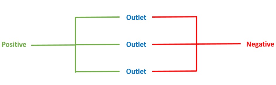
Flow of Current is Multidirectional
A parallel circuit is a closed circuit in which the electrical current flows in two or more directions.
The devices that have been tapped into the circuit loop are linked in a column formation. If one of the devices fails or becomes detached, the entire circuit will still continue to function.
Dominantly Used in Home Wiring
In terms of parallel vs series circuit, parallel circuits are far more popular than series circuits. This is notably true in the majority of domestic branch circuits that supply electricity to outlets, appliances, and light fixtures.
Pigtailing is Supported
Parallel configuration should be used in a normal home for outlets, switches, light fixtures, and other common 120-volt household circuits.
What Are the Differences Between Outlets Wired in Parallel Vs Series Configuration?
There are several key factors that differentiate between outlets that are wired in parallel and in series, apart from the varying magnitude of electricity and voltage.
So, what is the difference between an outlet wired in series and in parallel? They are mentioned in the chart below.
Wiring Outlets in Series Vs Parallel
| Features | Series Outlets | Parallel Outlets |
| Direction of Current | Unidirectional | Multidirectional |
| Voltage | Divided among outlets | All outlets receive the same voltage |
| Current | All outlets receive the same current flow | Divided among outlets |
| Preference for Home Use | Not Preferred | Preferred |
| Power Consumption | Power consumption of each outlet decreases with each additional component. | Power consumption of each outlet remains the same. |
| Power Distribution | Rear outlets are supplied less power than outlets at the front. | Equal power is supplied to each outlet. |
| Electrical Code Guideline | Goes against the guideline | Is advised to use, by the guideline. |
| Effect on Other Outlets | Damaged outlet prevents current flow. | Damaged outlet does not hinder current flow. |
| Impact of a faulty outlet | Can affect all outlets | Only affects that outlet |
| Ease of installation | More complex | Easier |
| Suitability for large loads | Poor | Better |
How Does the Circuit Configuration Affect the Outlets?
The circuit configuration affects all of the outlets in various manners. It depends on the factors mentioned above as well the components that have been used in the installation. These are:
Direction of Current:
When outlets are connected in series, current only has one way to flow, hence when one hindrance occurs in the circuit; all the outlets cease to work.
But in outlets that are wired in parallel, current flows in more than one direction.
Voltage:
The difference between series and parallel outlet configuration is that, the incoming voltage is split into the outlets in series configuration.
On the other hand, the voltage between parallel outlets is always the same as the supplied input voltage.
Current:
In outlets connected in a series arrangement, the current is always the same. The current, on the other hand, is shared among the parallel connected outlets.
Preference for Home Use:
A common question that arises is, “Are household circuits parallel or series?”
Series configuration for outlets in households is strictly discouraged. Parallel configuration should be followed for outlets in households.
Power Consumption:
With each new component in the series configuration, the power consumption of each outlet reduces. In a parallel setup, however, the power consumption of each outlet stays the same.
Power Distribution:
Power distributed among outlets is uneven in the series configuration, as rear outlets receive less power.
But in a parallel configuration of outlets, each outlet is distributed the same amount of power.
Electrical Code Guideline:
Connecting outlets in series violates the electrical code. It is evident that parallel wiring is the safest and most efficient option.
These key factors must all be taken into consideration before continuing with any electrical tasks such as, how to convert 3 phase to single phase 220v etc.
How to Determine the Best Circuit Configuration for Your Electrical System?
There are a few factors to consider when determining the best circuit configuration for your electrical system.
Number of outlets:
If you have a large number of outlets that need to be powered, parallel wiring may be more suitable as it allows for multiple paths for electricity to flow through.
Load requirements:
Parallel wiring is generally better suited for large loads as it can handle more power without affecting the voltage at the outlets.
Series wiring, on the other hand, is not suitable for large loads as it can result in a decrease in voltage at the outlets.
Ease of installation:
Parallel wiring is generally easier to install as it involves connecting each outlet separately to the power source.
Series wiring is more complex as it involves connecting the outlets one after the other in a single path.
Safety considerations:
In a parallel circuit, if one outlet becomes faulty, it will only affect that outlet and not the others.
This can be beneficial in terms of safety as it minimizes the risk of electrical fires or other hazards.
It is important to consult with a licensed electrician if you are uncertain about the best circuit configuration for your electrical system.
Summary
While parallel wiring is easier to install and better suited for large loads, series wiring can be more complex but may be necessary in certain situations.
It is important to comprehend the differences and choose the most appropriate one. Always consult with a licensed electrician if you are uncertain about the best wiring method for your electrical system.


![Outlet Stopped Working Breaker Not Tripped! [Ssolved]](https://wiringsolver.com/wp-content/uploads/2022/04/Outlet-Stopped-Working-Breaker-Not-Tripped.jpeg)